The PC817 is a four-pin integrated circuit. The IC is very small in size and looks like an SMD diode or other components. In this article I’m sharing all the information related to this optocoupler IC for better understanding. Its working, pinout, common circuit diagram, and specifications are discussed.
What Is a PC817 Optocoupler?
The PC817 is a general-purpose photocoupler IC; it contains an infrared LED and an NPN photo resistor placed in parallel. The IC provides a maximum of 5000 Vrms electrical isolation between the input and output voltage. This IC is most commonly used to separate the low-voltage driver section from the high-voltage section to protect the programming IC connected to it.
PC817 Optocoupler Working Principle
Input Current → Internal Infrared LED Light → Internal Phototransistor Conduction → Output Current
The infrared LED and photoresistor are arranged in parallel inside the IC. The infrared LED transfers the electrical energy in the form of light, which is received by the internal phototransistor. That time the transistor starts to conduct and allows the current passage through the collector and emitter pins of the internal transistor.
How the LED Inside PC817 Works
Input Voltage → Electrons Combine with Holes → Energy Released as Infrared Light → Photons Travel Across Barrier
The LED inside the optocoupler IC is an infrared LED. Which converts the electrical current (supply voltage) to anode and cathode into invisible energy, as in the form of light. This is due to the internal semiconductor property of the LED. In forward biasing, the electron moves to the cathode; the free electrons cross the junction and fall into the holes (the empty space), and they release the enrgy as in the form of IR light.
How the Phototransistor Works
Infrared Photons Strike Base → Electrons Knocked Free → Internal Base Current Generated → Collector-to-Emitter Conduction Opens
The transistor inside the PC817 is converting the incoming light energy back to the electrical energy. This photo transistor also acts like a normal NPN transistor, but it does not have a base pin. Instead of a base pin, it receives the light energy for the activation. When enough energy receives from the IR light, the transistor base region is activated and allows the large current to flow through the collector and emitter pins.
How Electrical Isolation Is Achieved in PC817
The electrical isolation in PC817 is achieved by energy transfer through light energy. The input and output sections are completely separated inside of the optocoupler IC. The internal LED and phototransistor sit face-to-face without any contact. Highly insulating epoxy or silicon resin is filled in the gap for proper separation. No electrons can move across the resin, and noise of the input supply cannot pass through it.
PC817 Optocoupler Pinout and Pin Configuration
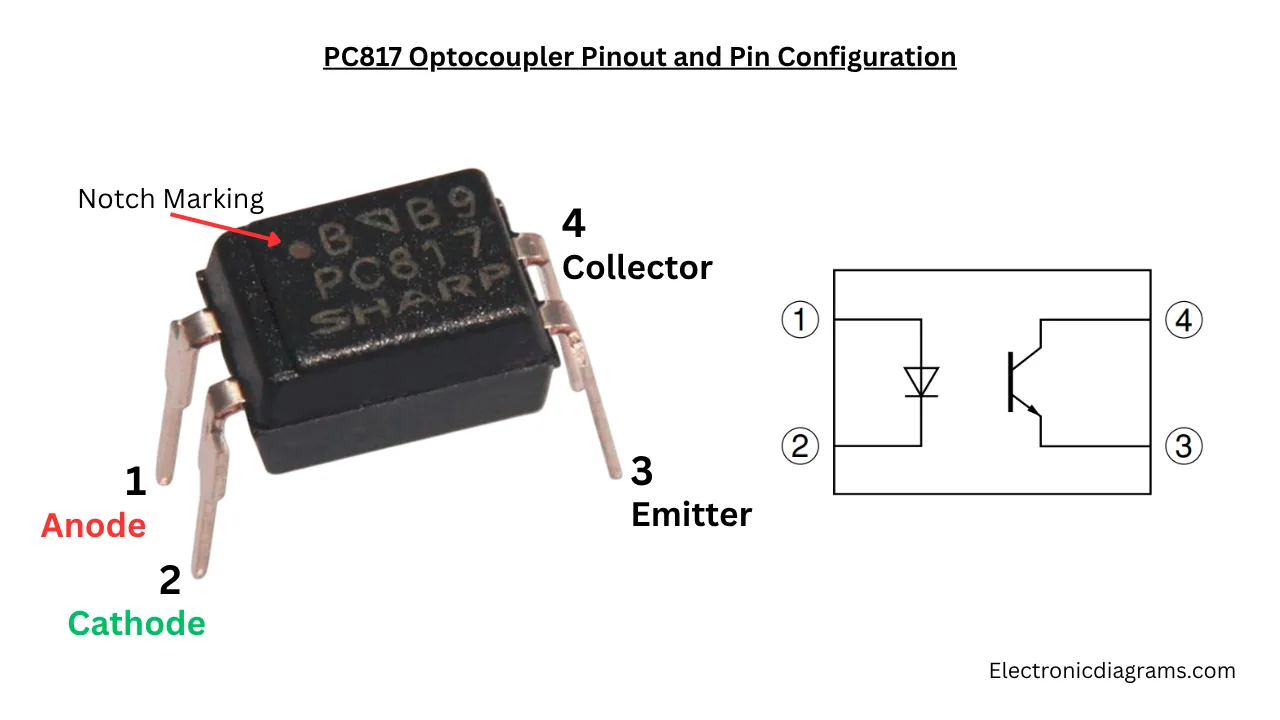
Hold the IC Notch or Dot is in left side and numbering facing to you. Count the pin from top left to right and bottom to top in right side pin as Pin 1 is Anode, Pin 2 is cathode, Pin 3 is Emitter and Pin 4 is Collector.
| 1 | Anode (A) | Positive terminal for the internal IR LED |
| 2 | Cathode (K) | Negative terminal for the internal IR LED |
| 3 | Emitter (E) | Output phototransistor emitter pin |
| 4 | Collector (C) | Output phototransistor collector pin |
Function of Each PC817 Pin
- Pin 1 is Anode which is the positive supply input pin to the internal IR LED.
- Pin 2 is cathode which the negative supply pin to the LED.
- Pin 3 is Emitter pin of photo transistor.
- Pin 4 is the Collector pin of photo transistor.
PC817 Optocoupler Specifications
- Isolation voltage is 5,000 Vrms.
- Minimum Collector-Emitter Voltage is 80 V.
- Maximum of 35V in some specific manufacturer variants.
- Forward Current of Input LED is 50 mA.
- Maximum Forward Voltage of the Input LED is 1.25 V typical (1.4 V max).
- Collector Current is about 50 mA.
- Maximum Current Transfer Ratio is 50% to 600% (varies by rank/grade).
- Power Dissipation is around 200 mW.
Isolation Voltage
The isolation voltage of optocoupler is the maximum electrical voltage can safely block by the optocoupler. The potential difference below the rated range is safest to protect the LED and detector transistor. PC817 comes with 5000 Vrms value.
Microcontroller Signal Isolation
The optical isolators are very useful electronic component to protect high voltage driver stage voltage spikes. The isolated input stage and output stage is avoids electrical nose and ground loops.
Testing Circuit Diagram To Confirm Internal LED and Phototransistor is working

While connect the supply to the LED we can not see it is transmitting light inside or not, but we can confirm it by using a multimeter to measure the current usage of the connected LED or output transistor conductivity.