Are you looking for a simple remote tester circuit? Most of the remote receivers are TSOP1738 and similar. In this article, I’m sharing a very simple circuit and it gives visual indication through an LED. Using this simple infrared signal detector circuit, you can easily build a remote signal detector project.
What Is an Infrared Remote Signal Detector?
This detector circuit is designed using a few electronic components to detect and indicate when the infrared signal is falling on the receiver. So, this device is useful for checking if a TV remote, AC remote, or other appliance remotes are working properly or not. Infrared signals cannot be seen by the naked eye; the circuit captures the signal and gives an LED indication.
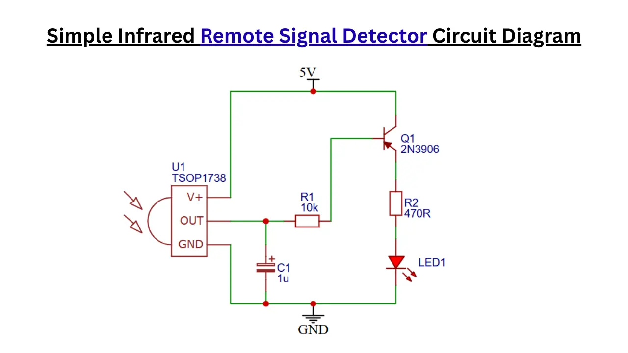
TSOP1738 Infrared Remote Signal Detector Circuit Diagram
Components Required
- TSOP1738 IR Receiver Module – 1
- 2N3906 PNP Transistor – 1
- 10 kΩ Resistor (R1) – 1
- 470 Ω Resistor (R2) – 1
- 1 µF Electrolytic Capacitor (C1) – 1
- 5 mm LED (D1) – 1
- 5V DC Power Supply – 1
- Breadboard or PCB – 1 (optional for assembly)
- Connecting Wires – As required
Role of Each Component in the Circuit
- TSOP1738 (U1) is Infrared receiver which detects infrared signals transmitted by a remote control.
- 2N3906 (Q1) PNP transistor which acts as a switch to drive the LED when an IR signal is detected.
- R1 (10 kΩ) resistor limits the base current flowing into the transistor.
- Resistor R2 of 470 Ω will limits the current through the LED to prevent damage.
- The Red LED1 will Provides a visual indication when an IR signal is received.
- Capacitor C1 of 1 µF will filters noise and stabilizes the receiver output signal.
- 5V Supply will Powers the entire circuit.
- GND is Provides the common return path for current flow.
How the IR Remote Signal Detector Circuit Works
When a Remote is pressed, the remote emits the infrared signal through the infrared LED on it. This signal is captured by the circuit we developed, because it contains a TSOP1738 Infrared receiver. When any IR signal is detected, it gives a small output voltage at the output pin. The output of the IR receiver is connected to a 2N3906 PNP Transistor.
When voltage reaches the base of the transistor, it turns ON and allows current to pass through it. This causes the LED to light up when the button is pressed on the remote. If the remote is not working, the circuit will not provide the LED indication.
Main Purpose and Applications of the Circuit
The main propose of the circuit is to detect the IR remote is working properly or not. When the remote transmit the signal and receiver capture it this will visually represents through the LED indication.
Advantages of This Simple IR Detector Circuit
- Simple and easy to build circuit design.
- Uses only a few low cost components.
- Provides instant visual indication of IR signal detection.
- Useful for testing TV, AC and other remote controls.
- Operates from a standard 5V power supply.
Testing the Circuit with a TV or AC Remote
Power the circuit using a 5V DC supply. At initial state their is no IR signals receiving from the remote so the LED is Turn OFF mode. Take the TV or AC remote , point towards the IR receiver and press any button, when button pressed the The signal transmitted and it receives by the circuit and turn On the LED, if LED is not turn ON after button pressed means the remote is faulty.
Possible Modifications and Improvements
- You can replace the indicator LED with a buzzer to provide an audible alert whenever an IR signal is detected.
- Add a microcontroller such as an Arduino and 16×2 display to decode and display the received remote control commands.
- Another option is use multiple LEDs or a display module to indicate signal strength, activity status, or different types of IR signals.