This 12V DC solid state relay circuit is used for controlling a 12 V DC operated device controlled using a 5V DC input. This circuit can isolate the large current section and low voltage driver section using optical isolation. This is the safest method for driver stage protection. In this article I’m sharing the simple circuit diagram of a solid state relay.
What Is a 12V DC Solid State Relay Circuit?
This Solid state relay circuit (SSR) can control 12V high current device switching by using a single 5V low current control voltage. This can be done using the principle of optical isolation of optocoupler IC. A small driving voltage is given to the input and controlling the large current at its output.
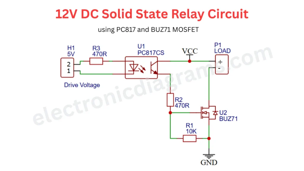
12V DC Solid State Relay Circuit
Components Required to Build This Circuit
| Designator | Component | Specifications / Value | Quantity |
|---|---|---|---|
| U1 | PC817 Optocoupler | Photocoupler / Optoisolator | 1 |
| U2 | BUZ71 MOSFET | N Channel Power MOSFET | 1 |
| R1 | Resistor | 10K | 1 |
| R2 | Resistor | 470R | 1 |
| R3 | Resistor | 470R | 1 |
| H1 | Input Connector | 5V Drive Voltage Terminal | 1 |
| P1 | Output Connector | Load Terminal | 1 |
| VCC | Power Supply | 12V DC | 1 |
| GND | Ground Connection | Common Ground | 1 |
Recommended Specification for This Circuit
- ✅ Input Control Voltage: 5V DC
- ✅ Output Load Voltage: Up to 12V DC (depends on MOSFET ratings)
- ✅ Provided by PC817 optocoupler
- ✅ Switching Element is BUZ71 MOSFET
- ✅ Resistor Power Rating is 0.25 watt minimum
Purpose of Each Components
- The main IC is PC817 which provides the optical isolation between input and output voltage.
- BUZ71 is N channel MOSFET and which control the high current switching when it receives Gate voltage.
- 470 ohms resistor connected in the low voltage and high voltage side, in low voltage side it use to limit the current reaches to the optocoupler LED. The high voltage side, 470 is used to control the current flow to MOSFET Gate voltage.
Working Principle of the 12V Solid State Relay Circuit
We can consider the two part in this circuit. First part is control signal and second in high current switching section.
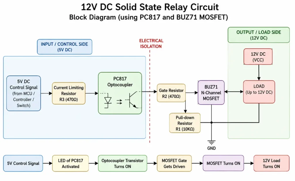
- The 5V DC supply is fed to the input the optocoupler IC LED ights.
- When the LED glow Inside the IC, which will turn s ON the inside phototransistor and which will allow the current to flow from collector to emitter.
- The emitter side BUZ71 N channel MOSFET is connected. In normal time the MOSFET is in OFF state and No current is passing through it.
- When the Photo transistor activated and current flows through it and reaches the MOSFET gate pin and MOSFET turns ON.
- The BUZ71 is ON and the current flow through the MOSFET and turn ON the connected 12V Device.
Applications of the PC817 and BUZ71 SSR Circuit
- Microcontroller based load control.
- DC motor and Fan swutching.
- In IoT and Remote Monitoring Devices this circuit can ON/OFF control through Wi-Fi, Bluetooth.