Are you looking for perfect audio amplifier circuit for your home or portable audio setup? This Mono amplifier circuit is based on the IC of LM1875. Which can deliver the maximum power output to the speakers in between 20 watt to 30 watt. The output power will varies based on the input voltage to the IC. In this article I’m sharing the Circuit diagram and PCB layout to build your self.
Advertisements
Why You Need To Choose
- This LM1875 Amplifier IC can deliver 20-30 Watt output at 8ohms speaker.
- Working input voltage is 25V dual power supply.
- Very small design and easy to assemble.
- Few number of external components so beginner friendly amplifier.
- Compared with any other audio IC LM1875 is Low cost and easily available.
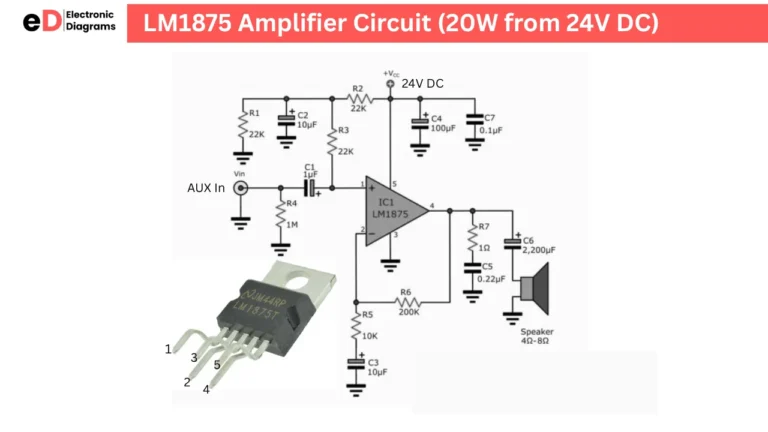
LM1875 Amplifier Circuit Diagram
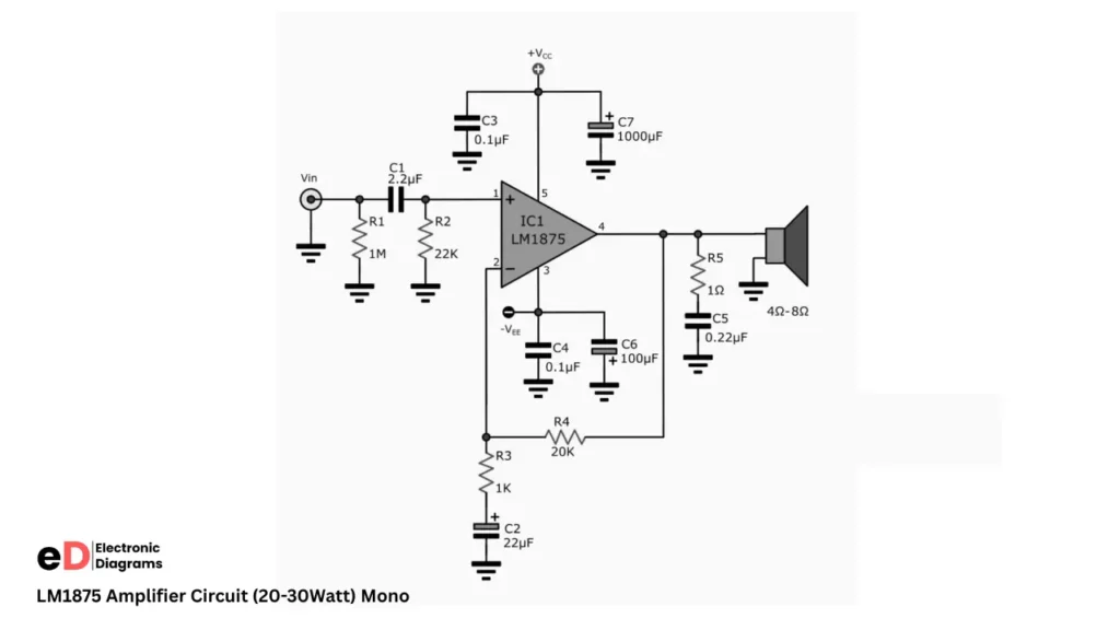
Circuit Diagram Explanation
- Pin number 1 of LM1875 IC is audio input pin, a 2.2uf capacitor is used to separate the pin and audio input source. 1M and 22K resistors are connected in the both legs legs the capacitor and it grounded. The 1 MΩ resistor (R1) is connected to ground at the input to provide a DC reference and prevent the input from floating, which reduces noise and hum when no signal source is connected.
- 22 kΩ resistor (R2) is also tied to ground to properly bias the non-inverting input and balance the input bias currents; together, these grounded resistors ensure stable operation, correct DC referencing, and clean signal amplification.
- The 20 kΩ resistor (R4) is connected between pin 2 (inverting input) and pin 4 (output) of the LM1875. This is the feedback resistor. Its role is to feed part of the output signal back into the inverting input, which sets the closed-loop gain of the amplifier together with R3 (1 kΩ).
Components Required
| Reference | Value |
|---|---|
| IC1 | LM1875 |
| R1 | 1MΩ |
| R2 | 22kΩ |
| R3 | 1kΩ |
| R4 | 20kΩ |
| R5 | 1Ω |
| C1 | 2.2µF |
| C2 | 22µF |
| C3 | 0.1µF |
| C4 | 0.1µF |
| C5 | 0.22µF |
| C6 | 100µF |
| C7 | 1000µF |
| Speaker | 4Ω – 8Ω |