The PC817 optocoupler IC has four pins, 2 pins are the LED pins and the other 2 pins are the photo transistor collector and emitter. In physical appearance we cannot say whether the component is working well or not. So to identify this, we are using a specially designed optocoupler PC817 tester circuit. This circuit will indicate whether it is working properly or not.
What is PC817 Optocoupler Tester
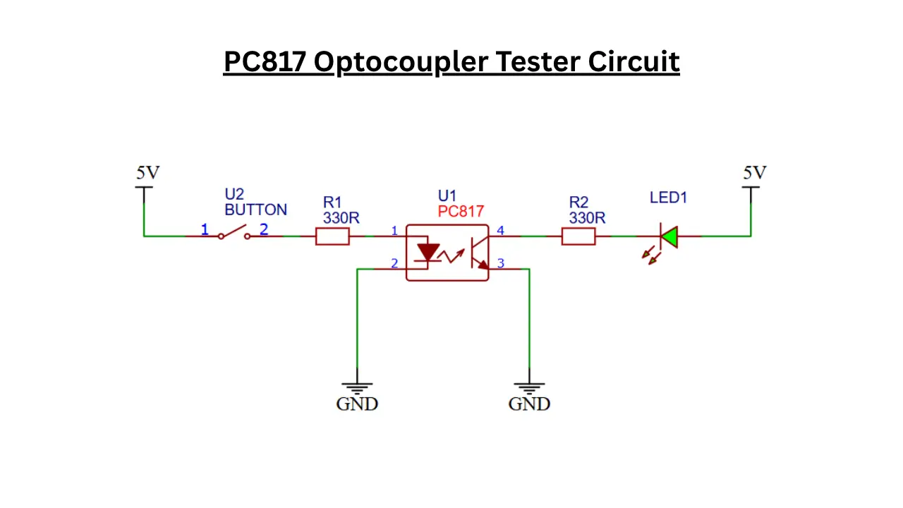
The specially designed LED based circuit gives a visual representation of the IC is working good or bad. The tester circuit need few external components like push button, LED and a resistor.
Optocoupler PC817 Tester Circuit
Components Required
- PC817 Optocoupler (U1) – 1×
- Push Button Switch (U2) – 1×
- 330Ω Resistor (R1) – 1×
- 330Ω Resistor (R2) – 1×
- LED Indicator (LED1) – 1×
- 5V DC Power Supply – 1×
- Connecting Wires – As required
- Breadboard or PCB – 1× (for assembly)
Role of Each Component
- PC817 (U1) is the optocoupler IC being tested.
- Push Button (U2) is used for providing the test signal.
- R1 (330Ω) will limits current through the PC817 input LED.
- R2 (330Ω) also limits current through the indicator LED.
- LED1 will shows whether the PC817 output transistor is switching correctly.
- 5V Supply will Powers the tester circuit.
How the PC817 Optocoupler Tester Circuit Works
The PC817 optocoupler IC based tester circuit is used to confirm the IC is working correctly or not. When the push button is pressed, the current flows through the button and it passes through a 330 ohms resistor and reaches the Internal LED anode pin. This will make the optocouplers internal infrared LED to activate the photo transistor. The 330 ohms resistor is used here as the current limiting and protects the internal LED from over current usage.
When the phototransistor is turned ON, the current can flow through the internal transistor. The LED connected in the collector side with a 330 ohms resistor and the current passed through it and turned on the LED. This confirms the PC817 is working properly. If the LED is not illuminated means the PC817 is not working properly. The expected results when switch in different condition is given below,
| Button State | PC817 Condition | LED1 Status |
|---|---|---|
| Released | Any | OFF |
| Pressed | Good PC817 | ON |
| Pressed | Faulty PC817 | OFF |