Do you want to safely control a 12V DC motor from a low power signal voltage, such as a microcontroller or other IC? This simple circuit, based on a PC817 optocoupler, can do this. The IRF1405 power MOSFET is also used to control the motor’s high current operation. The PC817 provides optical isolation between the driver stage and the power stage, so you don’t need to worry about damaging the driver IC.
Overview of the PC817 and IRF1405 Motor Driver
The circuit can control the high current DC motor from a small 5V DC supply from a microcontroller or other IC. The IC cannot directly handle the motor, so an optoisolated circuit is designed and used. The optoisolator provides proper optical isolation and protects the driver stage if any short circuit occurs in the power stage.
Opto-Isolated MOSFET Motor Driver Circuit
Components Required
- PC817 Optocoupler – 1
- IRF1405 N-Channel MOSFET – 1
- 10Ω Resistor – 1
- 10kΩ Resistor – 1
- 12V DC Motor – 1
- Flyback Protection Diode (e.g., 1N5408, FR107, or similar) – 1
- 12V DC Power Supply – 1
- LM3916 Output Signal (or any compatible control signal source) – 1
- Connecting Wires
- PCB or Breadboard (for assembly)
Function of each component in the circuit
- The PC817 IC provides the electrical isolation between the control circuit and motor driver stage.
- Power MOSFET of IRF1405 i acts as the main switching device for the motor.
- Resistor of 10Ω resistor limits the gate charging current to the MOSFET.
- 10kΩ resistor will pulls the MOSFET gate to ground when no control signal is present.
- 1N4007 is Flyback diode and which will protects the MOSFET from voltage spikes generated by the DC motor.
- The 12V DC motor is the load being controlled.
How the Circuit Works
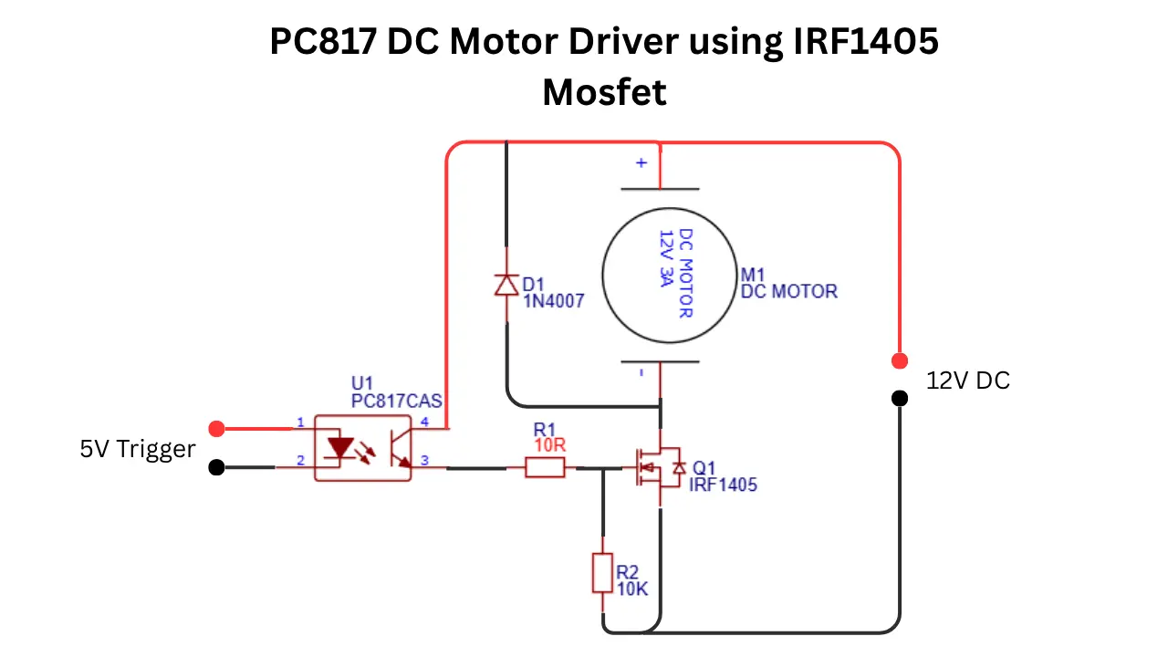
The circuit is built with a PC817 optocoupler and an IRF1405 power N channel MOSFET to control a 12V DC motor from a low-power control signal. The optocoupler provides electrical isolation between driver stage and power stage, which will help to protect the control circuit from voltage spikes and noise generated by the motor.
When a control signal is applied to the input side of the PC817 IC , its internal LED will turn on. This will activate the phototransistor inside the optocoupler IC. When it activates and the current flows through the output side(internal phototransistor) of the device.
Pin number 3 of optocoupler is the output pin. This output pin from the PC817 IC is connected to the gate pin of the IRF1405 MOSFET through a 10 ohms resistor. This resistor limits the current in the MOSFET gate. As the MOSFET gate pin receives enough voltage, the MOSFET switches on and creates a low resistance path between the motor and ground.
Once the IRF1405 MOSFET turns on, the current flows from the 12V supply through the DC motor and MOSFET. This will cause the motor to run. Because the IRF1405 is designed for high current applications, it can efficiently handle the motor load with minimal power loss.
A 10kΩ resistor is connected between the MOSFET gate and source. This pull down resistor ensures that the MOSFET remains turned off when no control signal is present which will also prevent accidental motor operation.
The 1N4007 diode is connected across the motor and acts as a flyback protection diode. When the motor is switched off, it generates a reverse voltage spike that could damage the MOSFET. So the diode safely dissipates this energy and protects the circuit components.
Applications
- DC motor speed control systems.
- Automatic cooling fan controllers.
- Battery charging indicators with motor control.
- Industrial automation projects.
- Robotics and small robotic vehicles.
- Conveyor belt motor control circuits.
- Microcontroller-based motor switching.
- Arduino and Raspberry Pi motor interfacing.
- Home automation systems.