Every electronic enthusiast and beginners in electronics loves to build simple electronic circuits. This 2 transistor LED flasher circuit is simple and easy to build. This LED project uses two BC548 Transistor, two LED’s, capacitors and resistors to create a visually engaging blinking LED lights. This circuit is specially designed for beginners and hobbyists. This circuit demonstrates the fundamental principles of electronics and oscillation circuit. This project is excellent educational tool and a fun way to add a bit of sparkle to your projects.
Components Required
| Component | Symbol | Value | Quantity |
| LED 1 | D1 | (Red LED) | 1 |
| LED 2 | D2 | (Green LED) | 1 |
| Resistor 1 | R1 | 47kΩ | 1 |
| Resistor 2 | R2 | 47kΩ | 1 |
| Capacitor 1 | C1 | 47µF | 1 |
| Capacitor 2 | C2 | 47µF | 1 |
| Transistor 1 | Q1 | BC548 | 1 |
| Transistor 2 | Q2 | BC548 | 1 |
| Power Supply | V+ | +3V | 1 |
| Ground | GND | 0V | 1 |
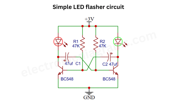
Circuit Diagram
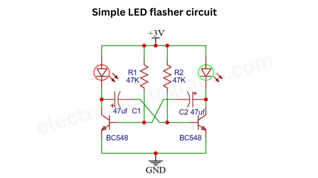
Connection
In this giver circuit diagram two BC548 NPN transistor are cross coupled to create an astable multivibrator. Which is working as an oscillator. The positive 3V DC is connected to the anode of LED and Resistor R1 and R2. The cathode of LED1 is connected to the collector of transistor BC548, while the cathode of LED2 is connected to the collector of another transistor of BC548.
The base of the BC548 transistor is connected to the positive terminal of capacitor C1, and the other end of C1 is connected to the collector of Q2. Similarly, the base of second transistor is connected to the positive terminal of capacitor C2 and the other end of C2 is connected to the collector of transistor. The emitters pins of both BC548 NPN transistors are connected to the ground.