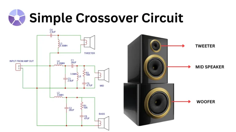
For a high fidelity’s speaker system a 3 way crossover is essential to optimize its sound reproduction through speakers. so in this article I’m sharing a simple crossover circuit for split audio signals into three different frequency band of Low frequency for bass, mid range for audio human vocal and speech sound and high for treble. This cross over is using after the audio amplification or in speaker like, so this setup is called passive crossover setup. In this passive crossover circuit consist of some inductor coils, resistors and capacitors.
Components Required
| Component | Value | Function |
|---|---|---|
| C1 | 28 µF | Midrange bandpass capacitor |
| C2 | 28 µF | Bass low-pass filter capacitor |
| C3 | 2.8 µF | Midrange high-pass filter |
| C4 | 2.8 µF | Tweeter high-pass filter |
| C5 | 4.7 µF | Midrange Zobel network capacitor |
| C6 | 47 µF | Bass Zobel network capacitor |
| L2 | 3.5 mH | Bass low-pass filter inductor |
| L3 | 0.35 mH | Tweeter high-pass filter |
| L4 | 0.35 mH | Midrange high-pass filter |
| L5 | 3.5 mH | Midrange bandpass filter |
| R1 | 10 Ω | Bass Zobel resistor |
| R3 | 10 Ω | Midrange Zobel resistor |
| Tweeter | 8 Ω (typical) | High-frequency speaker |
| Midrange | 8 Ω (typical) | Midrange speaker |
| Woofer (Bass) | 8 Ω (typical) | Low-frequency speaker |
Circuit Diagram

Circuit Connection and Working Principle
amplifier speaker out is connected to the terminal labeled with “INPUT FROM AMP OUT.” This amplifier out signal contains all frequencies like high and low frequencies. so we need to separate these frequency and give separated frequency into proper speaker type to improve its performance. This passive filter circuit will separating the full-range signal into three separate frequency bands using passive filters. know how this works in bass path, midrange path and tweeter path connection,
Bass (Woofer) Path
The low frequency signal is filtered using a large inductor L2 (3.5 mH) and capacitor C2 (28 µF) to block high and mid frequencies. Additionally a R1 (10Ω) resistor and capacitor C8 (47 µF) is form a damping network to fine tuning the bass response. The filtered signal is then sent to the woofer speaker, which is optimized for low frequencies.
Mid range (Mid) Path
The midrange signal path uses inductor L4 (0.35 mH) to filter out high frequencies and capacitor C3 (2.8 µF) to block low frequencies. An additional LC network (L5: 3.5 mH and C1: 28 µF) is used to sharpens the midrange bandpass filter. Resistor R3 (10Ω) and capacitor C5 (4.7 µF) is used to form a Zobel network for impedance stabilization. This signal is then fed to the midrange speaker for optimized working.
Treble (Tweeter) Path
Treble path needs high frequencies which is denoted in KHz. The high frequency signal is routed through capacitor C4 (2.8 µF) and a inductor L3 (0.35 mH) to block bass and mid frequencies. This setup is only passes the treble signals. The signal is then directed to the tweeter, which is designed to reproduce high-frequency sounds with clarity.