“ Learn how to build a Class D audio amplifier for Subwoofer. 400 watt RMS output from a single Amplifier board, The perfect choice for Car Subwoofer or Home Theater system.”

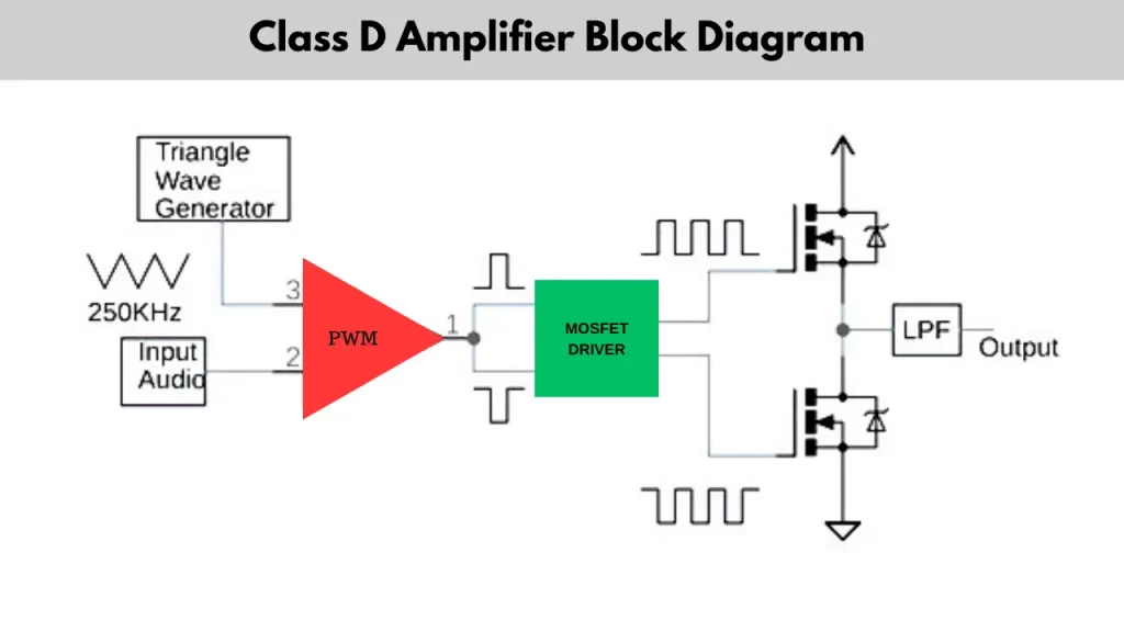
Before start to build a Class D audio amplifier, you need to know the basics of Class D amplifiers. You can easily understand what is mean by Class D amplifier. The Class D amplifiers are the very power efficient audio amplifier system, which works with pulse width modulation. it converts the input audio signal to a pulse form. The Class D audio amplifier is known as the next generation audio amplifier system or the digital audio amplifier. The 90 percentage of the Electrical current is converted into Audio because this audio amplifiers are known as energy efficient audio amplifiers.
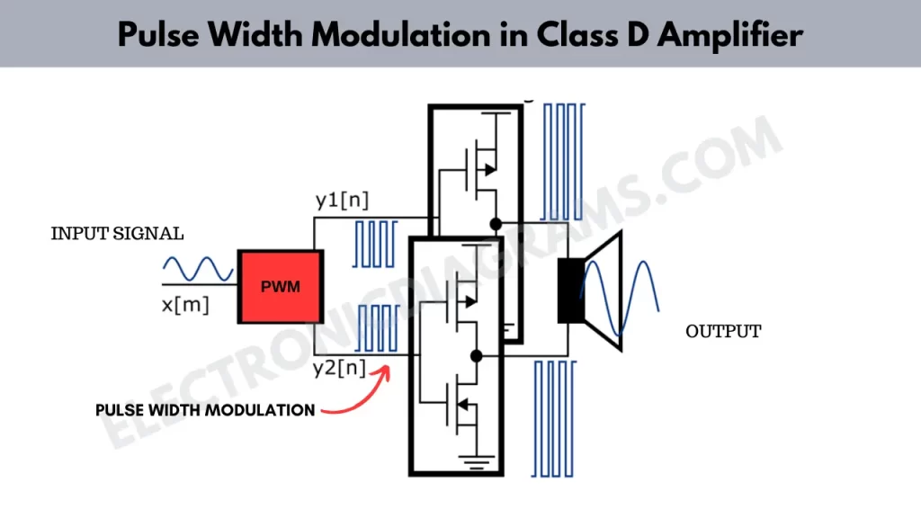
Pulse Width Modulation in Class D audio amplifier
the pulse with modulation is the technique that used to converting the analog signal into a digital pulse form. Which means that it varying the width of the pulse and keep the frequency constant. The PWM is also widely using in other electronic applications like controlling motor speed generating Analog signal from digital system. But in case of Class D audio amplifier system, the PWM is using as signal processing.

There are several stages are involving in signal processing which are input signal processing, digital personal generation, pulse generation, switching transistors or Mosfets, low pass filtering.
Input Signal Processing
You are input audio signal is in analog form. So it needs to be converted into a digital form using analog to digital converter. Once the circuit is converted the unknown log signal into digital form it may undergo to the digital filtering to removing unwounded frequency. This might be including high pass filtering to eliminating the low frequency noise or DC offset. After the input signal is processed the PWM encoded signal is then fed into the modulatory circuit of the Class D amplifier. The switching transistor or Mosfets amplified the signals efficiently.
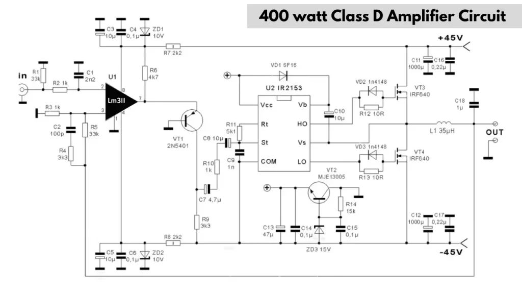
400 W Class D audio amplifier circuit diagram

The LM311 IC is voltage comparator. Typically it is not an amplifier but they can play crucial role in Class D audio amplifier. In this class D audio amplifier circuit, The audio signal is converted into PWM signal the LM311 can be used to compare the audio input signal with the high frequency, triangular Waveform.
The IR 2153 IC is a high voltage gate driver, Which is essential for driving the Mosfets stage of Class D amplifier. The ic which turned on and off the mostfets. The IR 2153 including various protection factors such as under voltage lockout and over current protection.
The Lus filter is reconstructing the audio signal from the PWM waveform The filter which removes the high frequency components from the audio signal. The IR 2153 IC is suitable choice for building the power stage of Class D audio amplifier disease due to its high voltage capability and built-in oscillator.


So which components that generate the triangular wave?
I didn’t see any triangular wave generator
But i think this comparateur used a technical that by comparing output amplier to input, it generate low high to rise or fall main signal