The adjustable voltage supply device is needed for testing and controlling of ant electronic device or circuits. so i decided to build an efficient power supply circuit with adjustable voltage. This adjustable DC power supply circuit will helps to test and check your electronics projects? This LM317 voltage regulator circuit is gives a variable output voltage with both coarse and fine adjustment controls, so this project is very helpful for hobbyists, students, and engineers in electronics.
This LM317 IC based power supply, it will converts an AC input to a stable, regulated DC output ranging from 1.25V to 30V. Also consist of bridge rectifier, filter capacitors, and protection diodes. this design ensures safe and smooth operation, while dual potentiometers allow precise voltage tuning. Whether you’re powering Arduino boards, testing components, or building a lab bench power supply, this circuit is the perfect solution.
LM317 Voltage Regulator
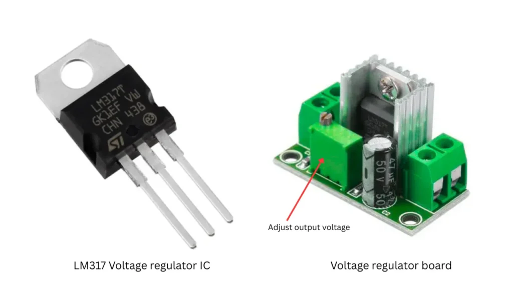
LM317 is a popular voltage regulator IC, which gives a stable or adjustable voltage in. This IC is most common in DIY electronics projects, power supply designing and branch power supply circuits. The LM317 IC can able to provide an output voltage of 1.25V to 37V. so this IC based circuit is also called as variable power supply. The output voltage is depending on the input voltage and connected components of the circuit. The IC based circuit deliver current of 1.5A in output. So you need to attach a large aluminium heat sink to the back side of voltage regulator for a good heat dissipation.
LM317 Pinout
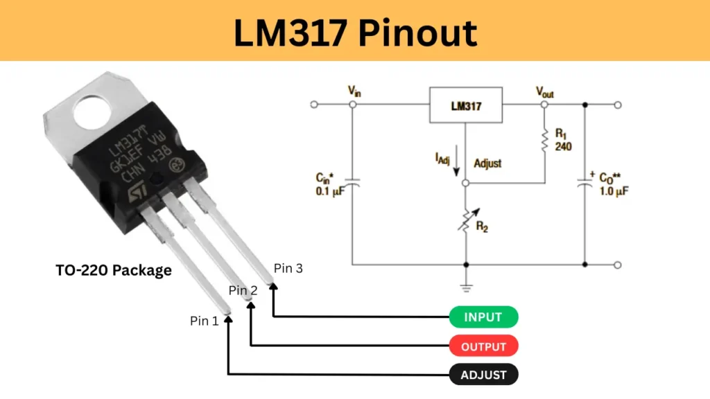
| Pin Number | Pin Name | Function |
|---|---|---|
| Pin 1 | Adjust | Adjusts the output voltage |
| Pin 2 | Output | Output voltage |
| Pin 3 | Input | Input voltage |
LM317 Output Voltage Formula
Vout = Vref(1+R2/R1)Iadj.R2
- Vout is output voltage
- Vref is reference voltage which is typically 1.25v
- R1 and R2 is resistors used in voltage divider circuit of IC.
- Iadj is adjut pin current
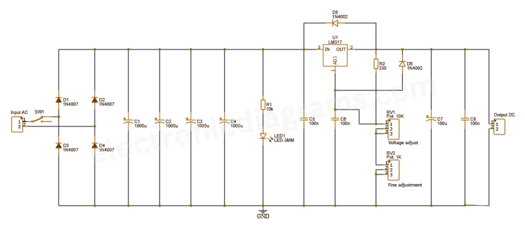
Circuit Diagram
Components Required
| Component | Value/Part Number | Description |
|---|---|---|
| D1 – D4 | 1N4007 | General-purpose rectifier diodes (bridge rectifier) |
| D5, D6 | 1N4002 | Protection diodes for LM317 |
| U1 | LM317 | Adjustable voltage regulator IC |
| C1 – C4 | 1000µF / 35V | Filter capacitors for smoothing DC |
| C5 – C6 | 100nF | Bypass capacitors for stability |
| C7 – C8 | 100µF | Output filter capacitors |
| R1 | 10kΩ | Current limiting resistor for LED |
| R2 | 330Ω | Resistor for voltage adjustment |
| RV1 | 10kΩ Potentiometer | Coarse voltage adjustment |
| RV2 | 1kΩ Potentiometer | Fine voltage adjustment |
| LED1 | 3mm LED | Power indicator |
| SW1 | SPST Switch | Power ON/OFF switch |
| Input AC | ~12V–24V AC | Transformer secondary (AC input) |
| Output DC | Variable (e.g., 1.25V–30V) | Regulated DC output |
Construction and Working
Connect the transformer connection to SW1 is a switch to turn the AC supply ON or OFF. The D1 to D4 (1N4007) is a bridge rectifier to convert AC to pulsating DC. The capacitor C1 to C4 is 1000 µF, which is using for filter and reduce ripple in the rectified DC.
The R1 (10k) and LED1 form a simple power indicator and C5 (100nF) provides additional decoupling/filtering near the regulator input.The U1 is the LM317 adjustable voltage regulator Ic. The diode D5 1N4002 is protects the LM317 from reverse voltage at its output.
The R2 (330Ω) and RV1 (10k pot) form the main voltage adjusting network. RV2 (1k pot) allows fine adjustment of the output voltage. A 100nF capacitor is improves the stability of the regulator. Diode D6 (1N4002) protects against back current from the output. In output filtering section capacitor C7 and C8 100µF will smooth the final output voltage.The output is taken from the connector marked “Output DC”.