Building a 12V power supply from AC mains is easy with a step down transformer and rectifier circuit. In this article i’m sharing a simple and commercial circuit diagram for converting AC voltage into DC voltage using transformer. This circuit consist of 12-0-12V center tapped step down transformer.
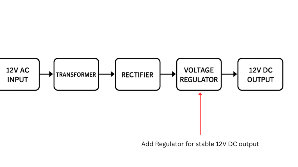
12V AC to DC Converter Block Diagram
Components Required
| Component | Specification/Value | Quantity | Description |
|---|---|---|---|
| S1 | ON/OFF Switch | 1 | Main power switch |
| F1 | 1A Fuse | 1 | Protection fuse |
| T1 | Transformer (220V to 12V CT, 2A) | 1 | Step-down center-tapped transformer |
| D1, D2 | 1N5402 Diode | 2 | Rectifier diodes |
| C1 | 2200µF, 25V Capacitor | 1 | Filter capacitor |
| R1 | 1.2KΩ Resistor (¼W or higher) | 1 | Current limiting resistor for LED |
| LED1 | 5mm LED (any color) | 1 | Power indicator |
| – | AC Power Cord | 1 | For 220V/117V AC input |
| – | Connecting Wires | As required | For circuit connections |
Circuit Diagram

Connection and Working
This given circuit represents the 12V ac to DC converter. This circuit consist of a 12-0-12V Transformer. The input voltage of 220v Ac to the trnasformer primary coil and from the secondary coil you will get 12V with center tapping. The tranformer secondary is connected with the full bridge rectifier circuit.
The D1 and D2 are the rectifier diodes using in this circuit which is 1N5402 arranged in ful rectification configuration. These two diodes rectifying the Halfs of the AC cycles and gives a pulsating DC out. The 2200uf capacitor will filtering the pulsated DC and storing the voltage and giving the 17V DC out. An LED is also connected with the circuit to know the transformer is turn on and it is proving the voltage to the output. A 1.2K resistor is using to power the LED.
This LED glows when DC voltage is present and it is serving as a power on indicator. The output voltage is approximately 17V DC, which is higher than the 12V RMS input due to the peak voltage and which is calculated using this given formula, RMS × √2 ≈ 17V